FNT Command C line details
All common cable types are defined in C line. This means that all physical cable connections can be mapped. Structured cabling that includes the patch and configuration cables is required in order to make use of the full functionality when making connections. Plausibility checks with regard to the medium (copper, glass) and connectors prevent input errors. Functions contained in the basic function set include bundled cabling for simultaneous insertion of multi-pair cables into several cabinets and the use of junction boxes.
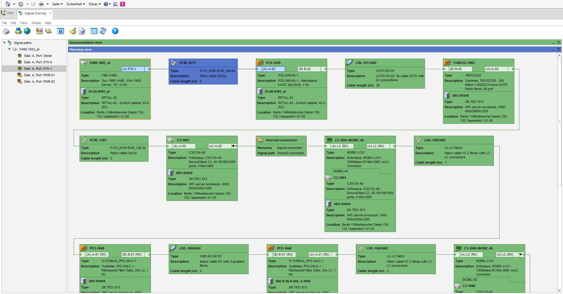
Signal tracing graphically displays the signal chain of a selected port. The devices and cables can be displayed as a block diagram. In order to be able to quickly distinguish between patch and configuration cabling, different icons are used. The user can select how signal tracing is represented by choosing from four different variants. It is possible to access different Command functions via each graphic object. The most important information from the database is displayed directly.
Representation of switch cabinets is true to life. The user can thus create a visual image of the actual cabinets. The graphics used are part of the delivery scope of the C base product library (CI Library). The graphics used are sensitive, which means that collision consideration, port assignment, and database information can all be queried directly. Switch cabinet planning and the option to select the planned or actual view are part of switch cabinet functionality. For each switch cabinet, four installation sides are available; the user can open several cabinets simultaneously. The wiring state of each port (planned/actual/locked) is displayed in graphical form. Direct patching in the switch cabinet is possible. The individual patch connections can be displayed graphically. Complete switch cabinets can be defined as an assembly and copied. It is also possible to create smaller, standardized assemblies. A distinction can be made between data distribution cabinets and telecommunication switch cabinets. Representation of telecommunication cabinets takes place with the aid of bays and rows.
Inventory Management covers creating and managing an inventory. C line offers a standard procedure for creating an inventory. First, master data for the objects is created and inventory numbers are reserved. After delivery, the devices are created in the database. An interface to SAP or other commercial software packages, as well as the use of barcode readers, has been implemented in several projects. Storage management enables storage locations to be created as required.
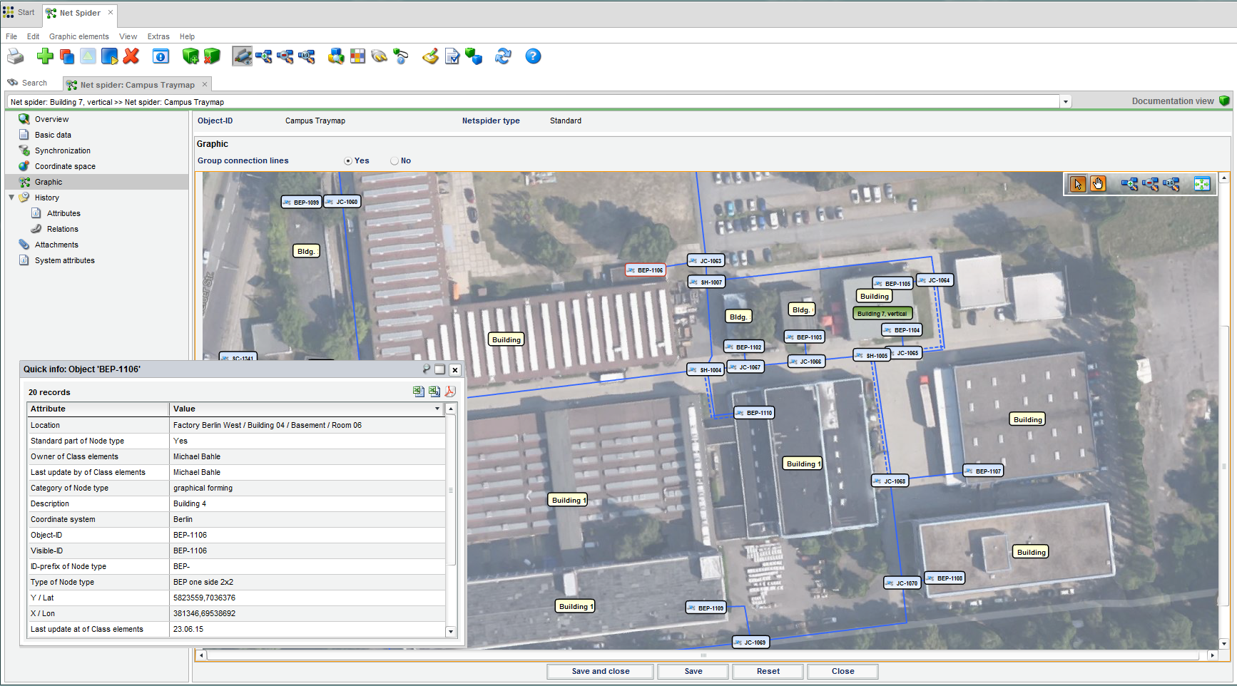
The netspider included in Command enables Command objects to be displayed graphically in the form of a netspider. The connected cables and subsequent objects can be determined for these objects and loaded manually or automatically into the graphic. Freely configurable labels can be used to display information, such as the type, location, and ID, for both objects and connections.
Internal connections of active components and directors are documented with the help of the Connection Matrix program section. To enable this, logical connections are established between the A-side and B-side ports of an object, with any combination being possible. Internal connections within modular devices are likewise possible.
Junction boxes are managed via the Junction Box program section. Cables can be inserted into junction boxes, with the fibers being placed in splice trays and then spliced. This functionality can be used for individual fibers or for multiple fibers (bundle). It is possible to install splitters and the corresponding cabling directly in the splice trays. The result of the actions is an easy-to-read splice plan, which can be used as an assembly plan.
All management and documentation of tray infrastructure takes place using Command’s Tray Management module. Both in-house-relevant infrastructure, such as sill channels, raised floors, riser trays, cable racks, etc., and regional or inter-regional routing (trenches, micro-ducts, standard ducts, etc.) are covered. It is also possible to assign tray sections or ducts to cables. This allows documentation of the geographical route of a cable. Section contents (ducts and cables) are shown in a table with all the required details. Ducts can be fully documented with details of the side and location (including utilization calculation). Easy-to-use routing mechanisms support the creation of complete tray and cable routes. A shaft editor can be used to graphically display and process all sides of shafts.

C line
Our products:
-
FNT CommandManage your IT and telecommunications infrastructure
-
FNT SustainabilityReduce your carbon footprint
-
FNT CommandMobileAccess the FNT Command Platform from any location and at any time
-
FNT Infrastructure Health & MonitoringEstablish the foundation of a resilient digital infrastructure
-
FNT AnalyticsBusiness Intelligence module for smart evaluations and analysis
-
FNT ProcessCenterManage infrastructure provisioning and change processes more efficiently
-
FNT IntegrationCenterSimplify, speed up, and lower the cost of software integrations
-
FNT EventEngineMonitor events and trigger targeted actions
-
FNT ServicePlanetTurn your IT into a key success factor
-
FNT StagingAreaSimplify data exchange between your systems
-
FNT GeoMapsImprove network management with location-based visualization and analysis of resource data
-
FNT ValuePackThe fastest way to reach your objectives
-
FNT GraphicCenterVisualize and analyze infrastructure and service data